S2 Know Your Device
2.1 Unboxing checklist
After unboxing, verify you have (actual kit may vary):
| Item | Description |
|---|---|
| Radar unit | Square housing |
| Bracket module | Side-mount kit: wall plate, pivot core (3-part pivot assembly), device-side disc (see S3.2) |
| Power | Type-C cable or adapter (DC 5V 2A) |
| Documents | Quick guide, warranty card, etc. (if included) |
2.2 Unit appearance & ports
How to read the figures
Front = dark gray sensing panel. Back = bracket side. WiFi and 4G share this shell; SIM is 4G only. PoE/Ethernet shell differs (not shown here).
Where things are
| Item | Location (front = sensing face) | Notes |
|---|---|---|
| Sensing face | Front | Dark gray panel, concentric groove border |
| MIC holes | Front bezel | Two holes: top and bottom of the border (voice intercom pickup) — left panel |
| Provision button | Left side (opposite the card/power side) | Vertical oval button, mid-lower on that side — Fig. 3 |
| Type-C (side) | Right side (port cluster) | Horizontal Type-C, mid height — Fig. 2 |
| T-CARD (SD) | Right side, below side Type-C | Cover toward the sensing face; labeled T-CARD — Fig. 2 |
| SIM | Right side, below T-CARD | Cover toward back/bracket; labeled SIM; 4G only — Fig. 2 |
| Type-C (back) | Back, lower-right area | Use either side or back Type-C — Fig. 4 |
| Side-mount pivot core | Back center | Pivot + deco 1 + deco 2 assembled + device-side disc — Fig. 4 |
Appearance & ports (illustration)
Left: sensing face + right-side Type-C / T-CARD / SIM. Right: left-side provision button + rear pivot core and device-side disc.
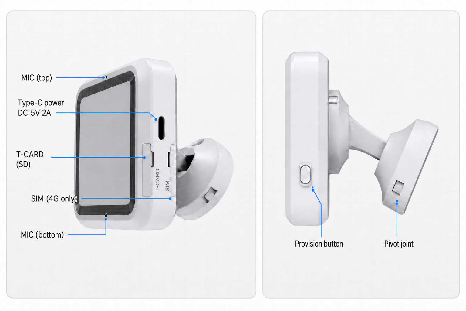
Back Type-C also available — use either side or back port. SIM slot: 4G only. Wall kit: S3 →.
Know the bracket module
- Unit rear (right panel): pivot core (3-part assembly) + device-side disc — usually already on the unit.
- Wall plate: part ① of the side-mount kit; slides out in S3 step 1 and is fixed to the wall separately.
2.3 First power-on (quick check)
You may power the unit before wall mount to see basic behavior:
- Connect Type-C 5V 2A (side or back — either port).
- Solid red right after plug-in — system booting; allow ~1+ minute.
- If not provisioned yet, red blinking often means no network — complete provisioning per the User Setup Guide.
- During normal operation the LED is usually off; off does not mean powered down.
Full LED sequence (online + provisioning modes): User Setup Guide (separate site).
2.4 Detection zone
Before mounting, know where the unit can sense. Tracking and fall detection use the same effective area (typical tilt mount at 30°).
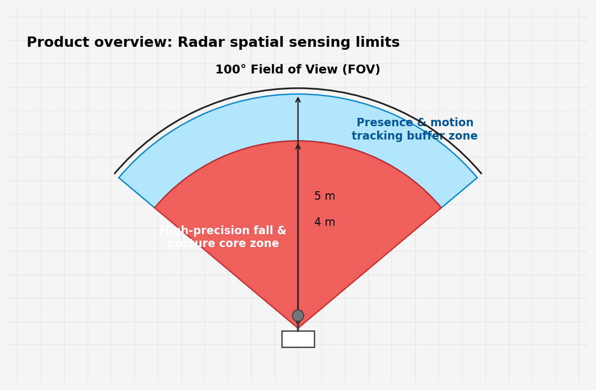
Everyday wording (FYI only)
You may hear these figures in conversation. For awareness only — not for choosing a mount point:
| Phrase | Meaning |
|---|---|
| FOV ≈ 100° | Rough sense of coverage width |
| Tracking ≈ 5 m | Rough how far presence/trajectory reaches |
| Posture / fall ≈ 4 m | Rough core sensing distance |
The fan diagram below is illustrative only — do not use it for placement:
Use for placement (authoritative)
When choosing a mount point, use this top-down view only:
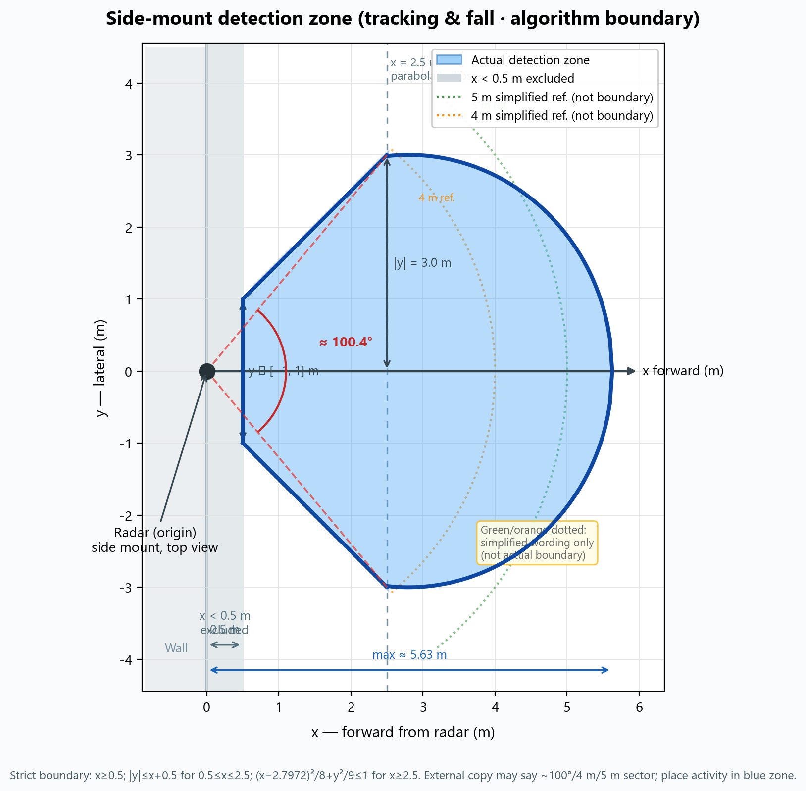
Blue = where detection works well.
| How to read | Guidance |
|---|---|
| Radar | Left side of diagram (on wall) |
| Effective area | Blue zone, into the room |
| Should cover | Bed, walkways, floor you care about inside blue |
| Weak coverage | Right behind the unit, along the wall — do not rely on it |
| Green / orange dotted | Rough “5 m / 4 m” talk only — not real boundaries |
Flat wall mount
Flat mount (0°) changes the shape; still keep bed/activity in coverage, and use S3.3 foot-of-bed wall in bedrooms.
Installers only need the blue-zone diagram above — no formula or engineering notes required on site.
2.5 Orientation & mount posture
Terms
| Term | Meaning |
|---|---|
| Mount height | Floor → radar center (vertical) |
| Down-tilt | Tilt 30° (preset); flat 0° (see S4) |
| Level | No roll (left/right tilt) |
| Plate hole line | Vertical |
| Bracket | Parallel to wall, vertical to floor |
| Power port | Prefer facing down after install |
| Forward | The sensing face (dark gray panel) — toward room activity when mounted |
| Wall side | Back of the unit against the wall; up must stay upright when mounted |
| Horizontal swivel | After mount, ±45° left/right (top view below); 30° down-tilt unchanged |
Before wall mount, fix the spatial layout: sensing face into the room, back against the wall, no roll. Below: tilt mount — back flush on a vertical wall, 30° down-tilt unchanged (flat 0°: S4). For back-rail “upwards here” at install time, see S3.4 step 5.
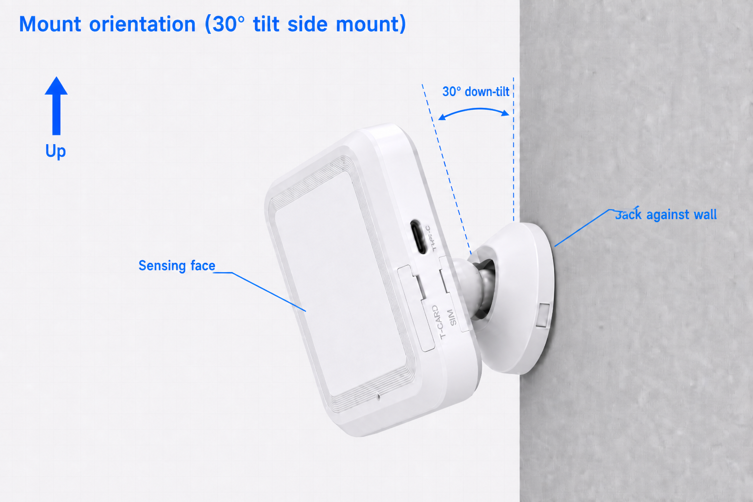
Up = true vertical; 30° down-tilt: right line ∥ wall, left line ∥ device back cover; sensing face = leader line to gray panel; back against wall = rear flush on vertical wall. MIC holes: S2.2 illustration.
Install modes (overview)
Details: S4 Height & angle:
| Mode | Height | Down-tilt |
|---|---|---|
| Tilt mount (recommended) | 2–3 m, typical 2.5 m | 30° |
| Flat wall mount | typical 1.5 m | 0° |
Tilt mount: level on wall, no roll; bedrooms on foot-of-bed side wall.
Horizontal fine-tuning after mount (±45°)
The pivot allows roughly ±45° horizontal swivel (about the wall-plate center — see top view). The pivot core is three STP parts assembled (pivot + deco 1 + deco 2). If the wall plate holes are vertical and the plate is level, you can rotate the unit by hand after mounting to aim the detection zone — useful in room corners — without re-drilling. 30° down-tilt is unchanged (set by the pivot core; yaw does not change pitch).
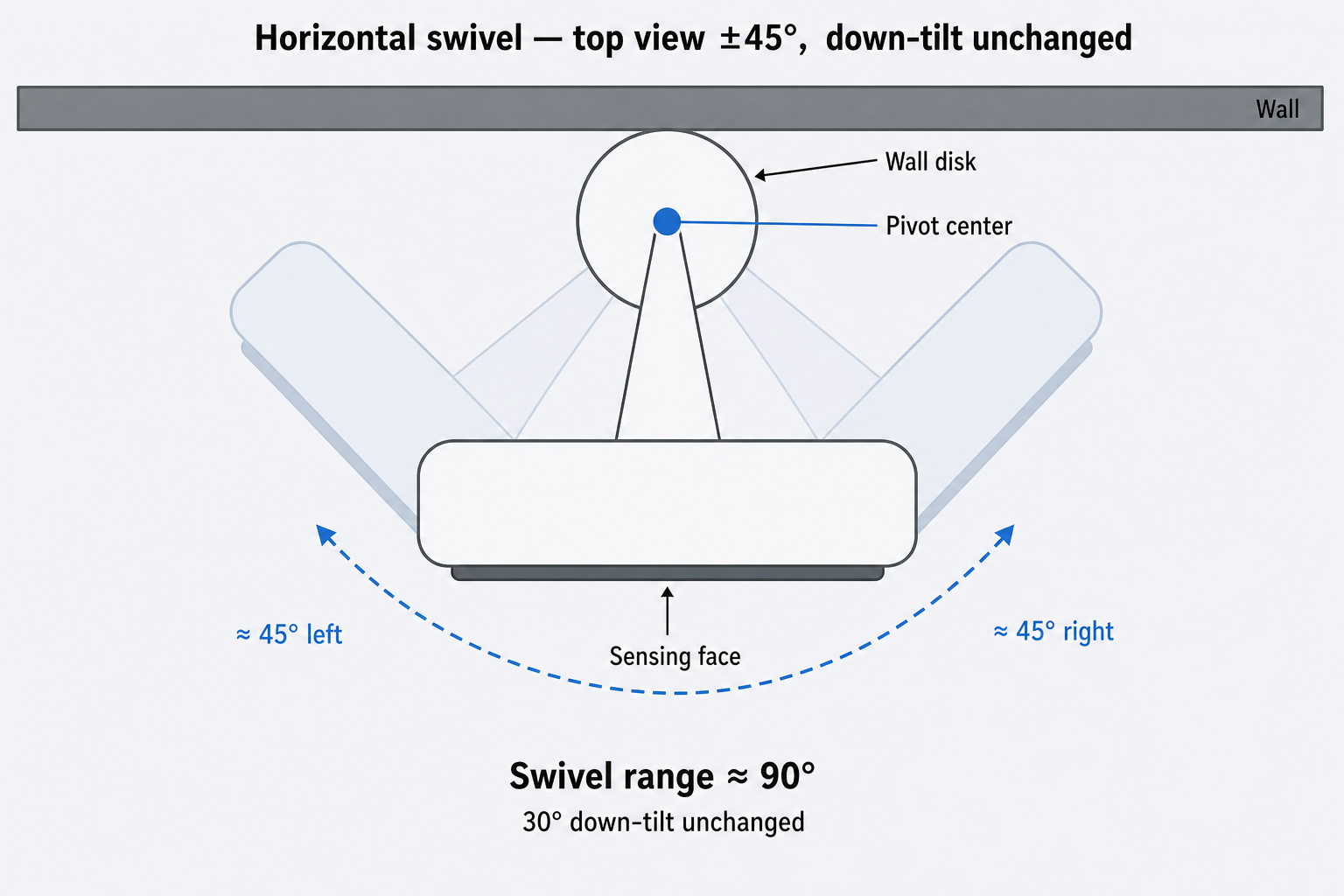
Top view: blue dot = bracket pivot (wall-plate center). Arm + unit rotate as a rigid body about this point; same arm length and device outline at all three angles. 30° down-tilt unchanged.
Alternatives: adhesive + plate; tripod ~2–2.5 m with 1/4" head (tilt scenarios).